|
Do Not Weld. Torflex axles contain rubber cords to provide the
suspension system and can be damaged by the heat generated from welding on
the bracket or the tube.
The following instructions describe methods that can be used to attach your
Torflex axles to the vehicle frame.
- The user must first decide where to place the axle(s) on the
trailer. The position of the wheel center relative to the CG
(center of gravity) will determine the final axle loading as well as the
hitch load.
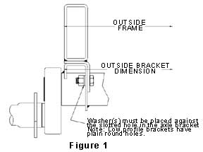
- Determine the method of attachment you wish to use. a) For
structural tube type frame rails, refer to figure 1 for the recommended
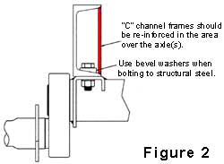
attachment. b) For "C" channel or "I" beam type
frame rails, refer to figure 2.
- Once the method of attachment is decided, the axle(s) must be
carefully aligned on the trailer frame. The axle(s) centerline
must be perpendicular to the longitudinal centerline of the
trailer. See figure 3.
Caution: Misalignment of the axle(s) can cause poor tracking and
accelerated tire wear.
Attachment to Structural Tube Type Frame
- Dexter Axle recommends the use of side mounting hangers when mounting
axles to tubular type frames. These hangers provide a convenient
means for bolting the axles in place. All of the necessary
components are included in the Side Mount AP kits listed in Chart 1.
- Refer to Chart 2 to find the mounting bracket dimensions of your
axles. This chart shows the dimensions from the wheel center to the bolt
holes of the brackets.
- The preferred way to use the side mount hanger is to pre-assemble the
hangers to the axle using the hardware provided in the AP kit.
Make sure the hangers are clamped firmly against the axle brackets and
the bolts are tightened to the torque specifications shown in Chart
1. Position the axle assembly on the frame rails in the desired
location and weld the side mount hangers to the frame.
- Axle bracket position is the distance as measured over the outboard
edges of the brackets. This dimension is usually matched to the
outside measurement of the frame members but depending on the type of
frame may not always be suitable. The preferred arrangement should
place the longest vertical section of the axle bracket directly under
the most rigid section of the frame member.
Side Mount Installation
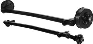
- Totally rubber-cushioned for smooth, quiet independent ride
- Easy installation with less maintenance
- Less transfer of road shock which insulates cargo from road shocks and
vibration
- Rubber cords compounded for maximum dependability and durability
- Load carrying cross member
- Self-damping action
- Independent wheel suspension system
- Low profile for maximum road clearance
- Various starting angles to control trailer height
- High and low profile brackets with optional mounting brackets
available
- Rubber cushioning eliminates metal-to-metal contact
- Shock absorption provided by the natural hysteresis of rubber
- Single or tandem axle assemblies
- Durable, wear-resistant components
Side mount hangers should be welded to frame with three (3) 1/4" fillet
welds, 2 1/2" long on each side of the hanger and a fillet weld on each
end. Welds should meet the quality standards of the American Welding
Society, D1.1 Structural Welding Code.
Chart 1
Attaching Parts Kits and Torque Specifications
| Axle Size |
A/P-Kit Top Mount |
A/P-Kit Side Mount |
Bolt Size |
Torque Lb-Ft. |
| #8 |
A/P-161-00 |
A/P-165-00 |
1/2" |
70-90 |
| #9 |
A/P-161-00 |
A/P-165-00 |
1/2" |
70-90 |
| #10 |
A/P-148-00 |
A/P-166-00 |
5/8" |
120-155 |
| #11 |
A/P-148-00 |
A/P-167-00 |
5/8" |
120-155 |
| #12 |
A/P-148-00 |
A/P-168-00 |
5/8" |
120-155 |
| #13 |
A/P-148-00 |
A/P-169-00 |
5/8" |
120-155 |
Side mount hangers and fasteners for mounting axle are provided in AP
(Attaching Parts) kit shown in Chart 1. Torque fasteners to levels
specified in Chart 1.
Attachment to "C" Channels or "I"
Beam Type Frame
-
Refer to Chart 2 to find the mounting bracket dimensions
of your axles. This chart shows the dimensions from the wheel
center to the bolt holes of the brackets.
-
Lay-out the bolt hole locations on the bottom flanges of
the frame rails. Make sure the hole pattern matches the mounting
brackets of your axles and is properly oriented to allow proper
alignment of the axle(s).
-
An alternative method for determining hole location is
to position the axle assembly in the frame rails, align it perpendicular
to the trailer centerline, clamp in place and transfer the holes
directly from the brackets.
-
Drill the holes through the frame rails and attach the
axle using the hardware provided in the AP kit. Tighten the bolts
to the torque specified in Chart 1.
Caution: When bolting to structural shapes that have
tapered flanges, bevel washers must be used to prevent uneven clamping and
bending of the fasteners.
Top Mount Installation
|